Soldering the components
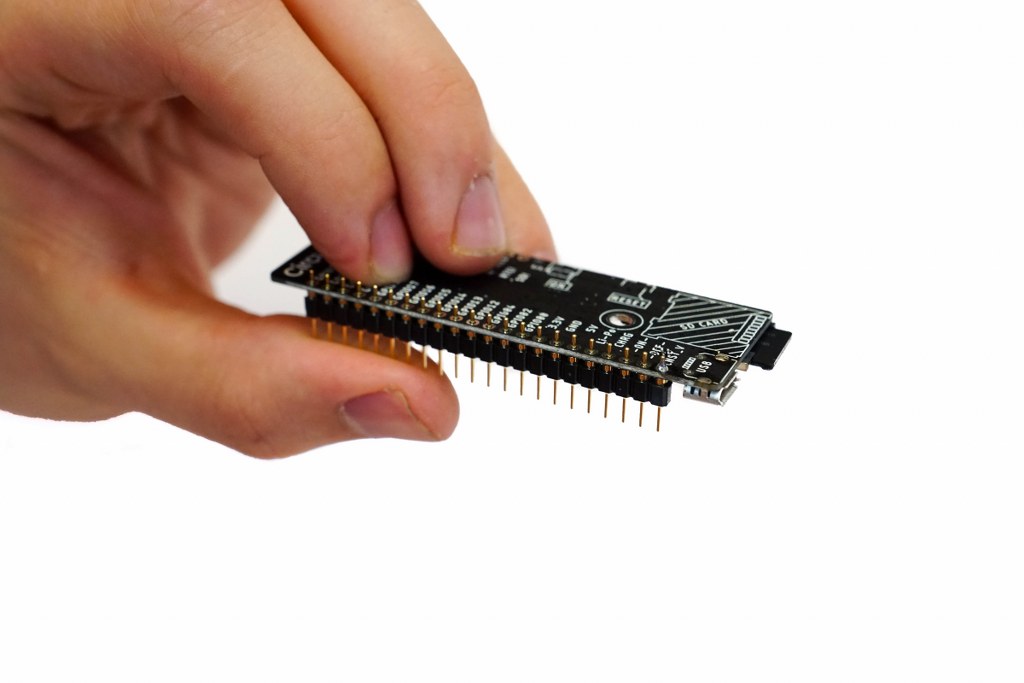
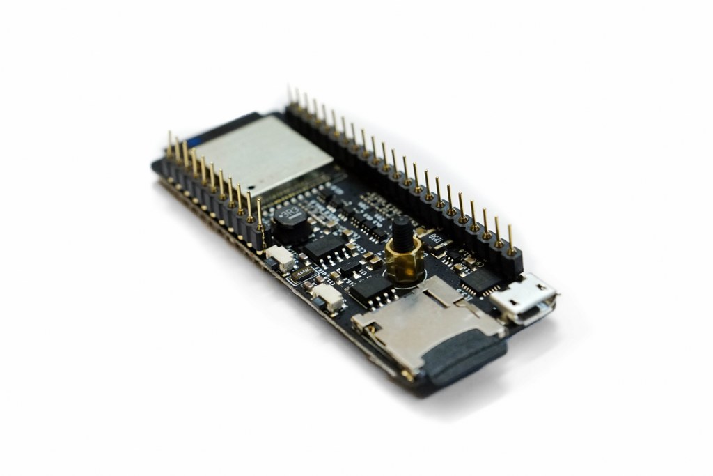
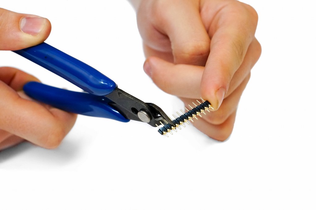
Step 1 – The Brain board
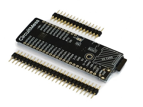
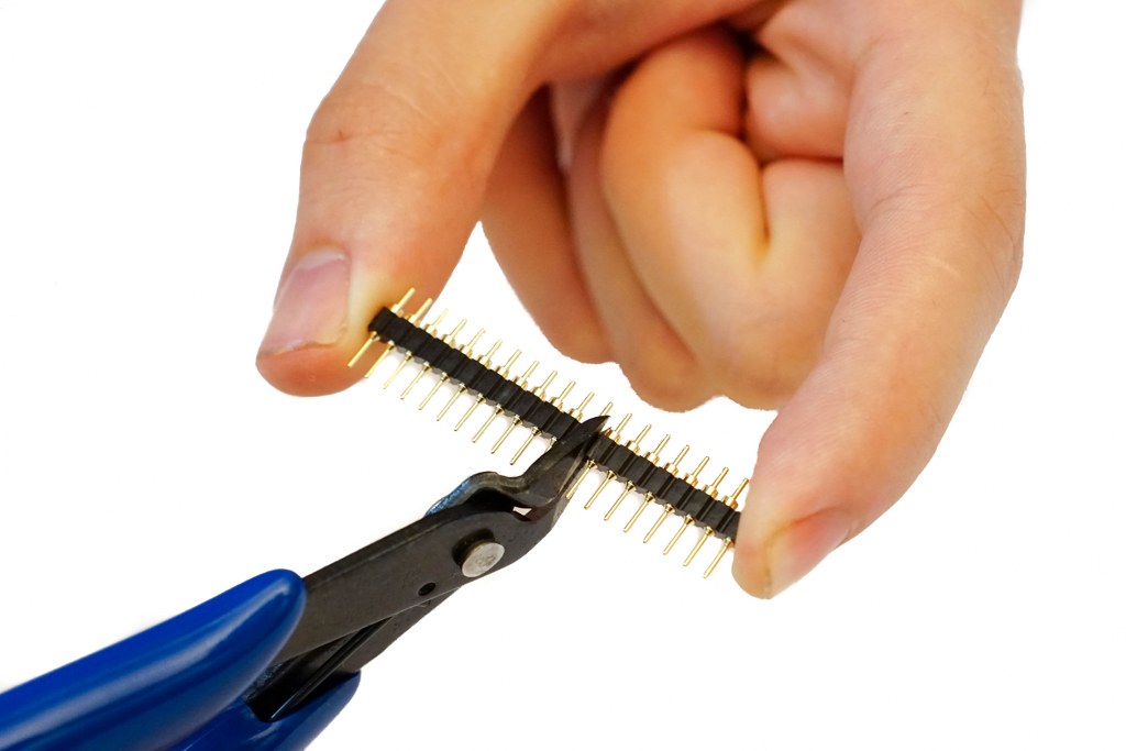
You'll notice that one row of pins is shorter than the other. Make sure that that you're soldering the row with the shorter pins to the board.
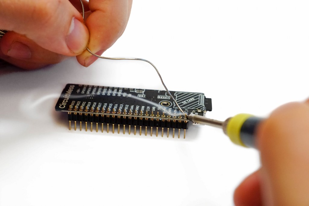
 If the header is vertical to the board, you can solder the rest of the pins.
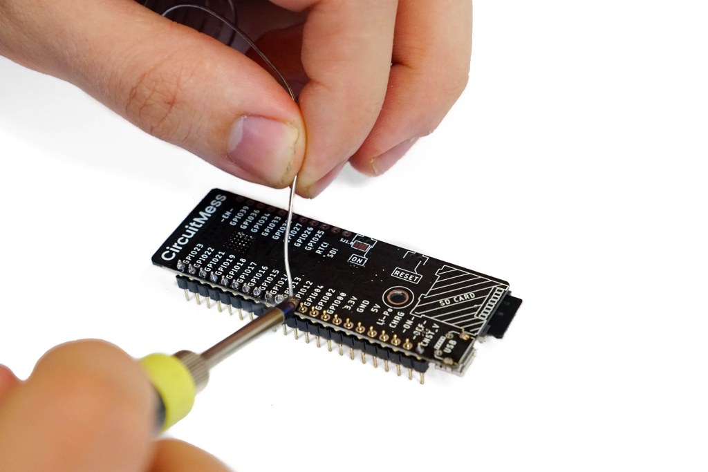
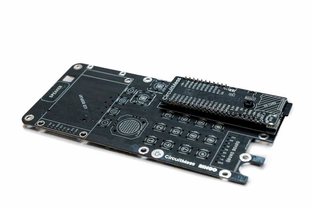
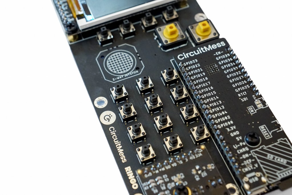
Step 2 – Attaching the Brain board onto the Main board 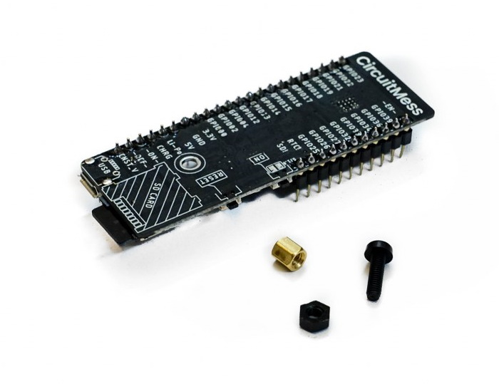
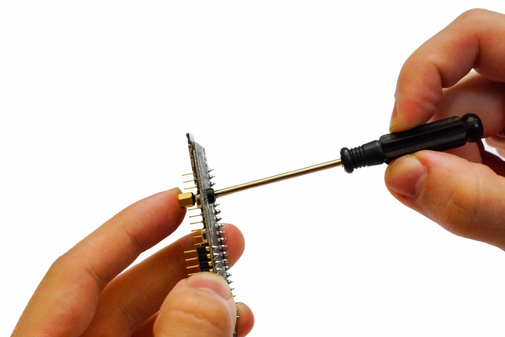
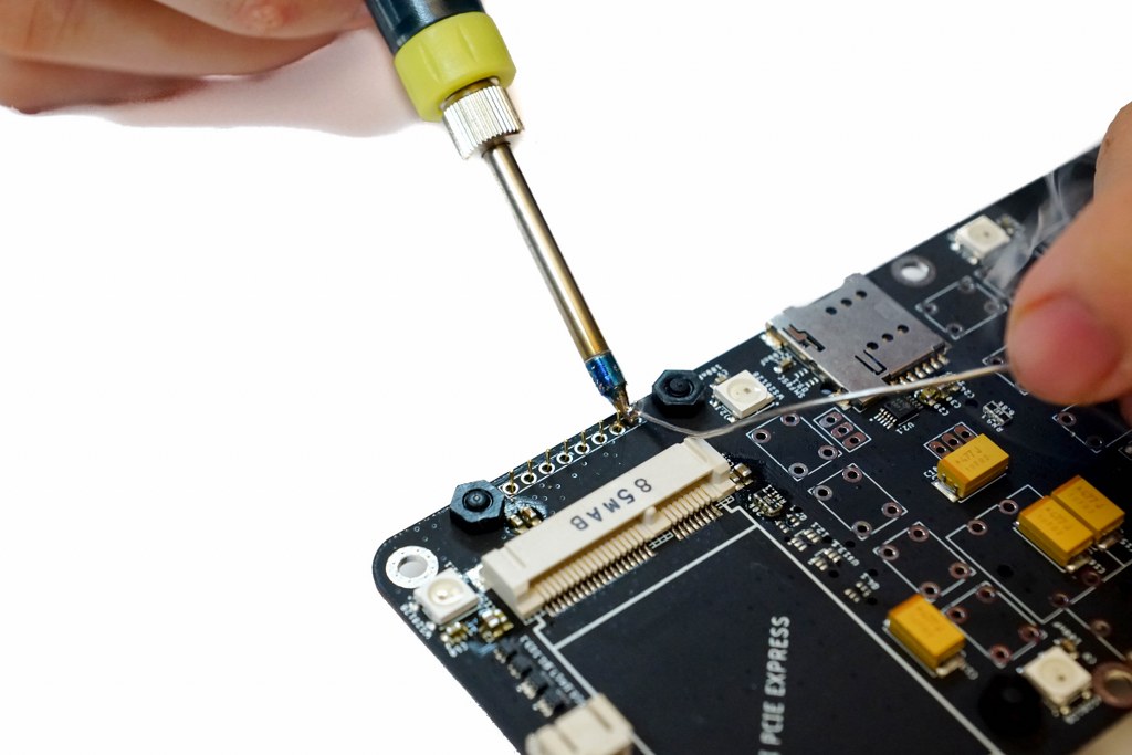
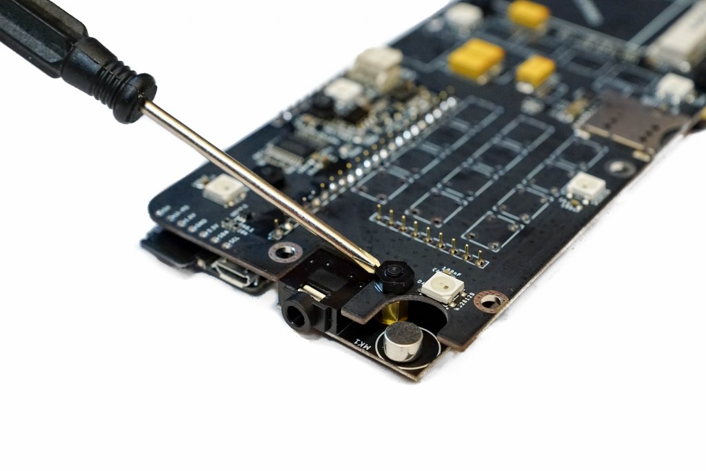
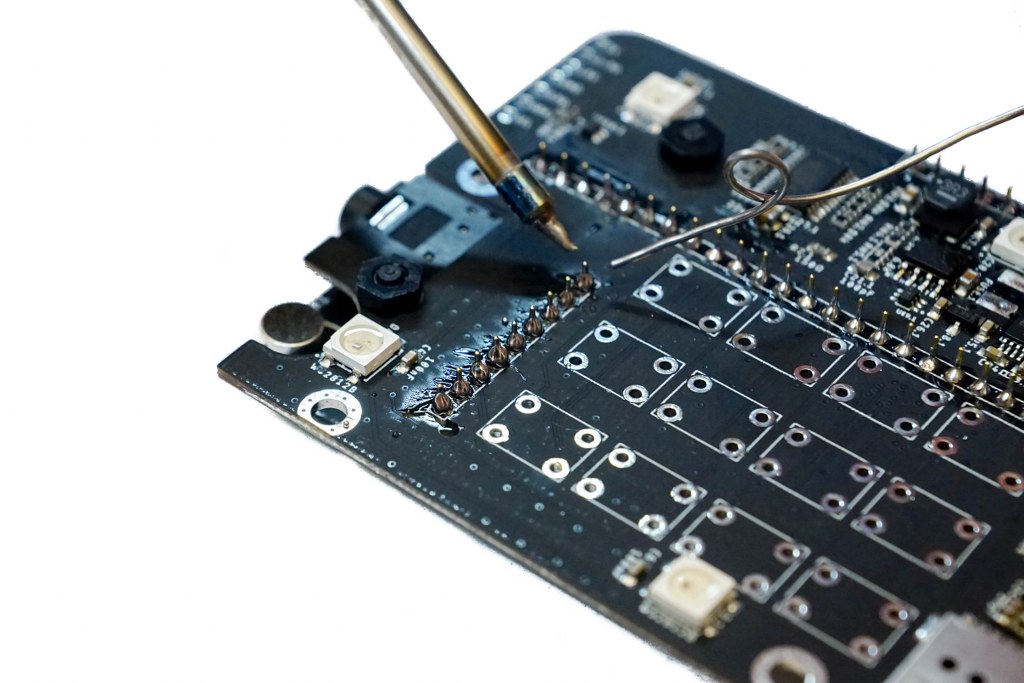
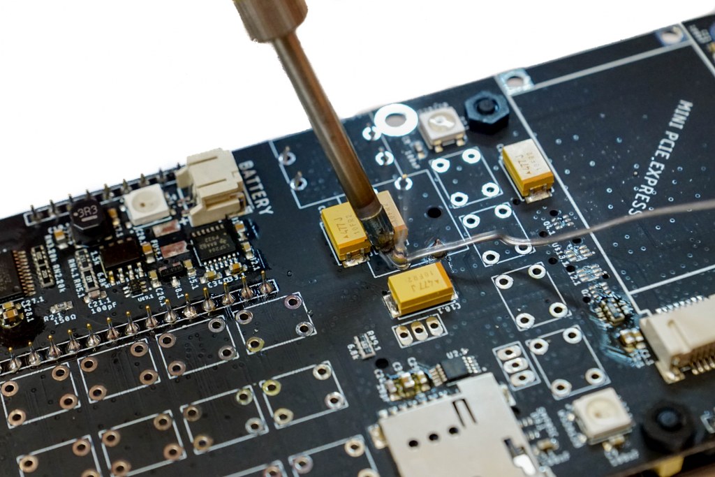
Step 3 – Soldering the Brain board to the Main board 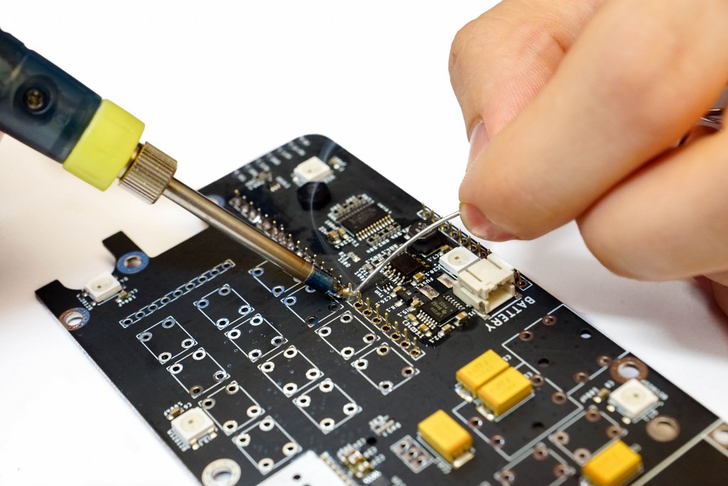
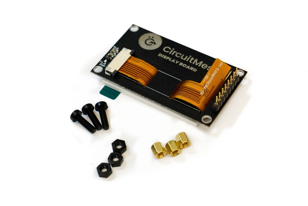
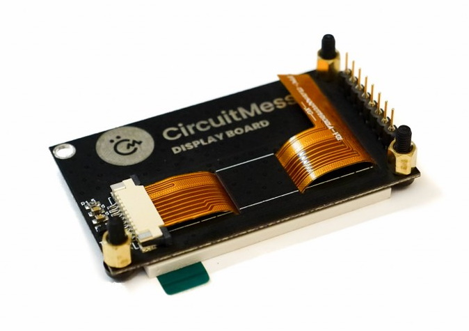
We need to do this in order to establish an electrical connection between the Brain board and the Main board. 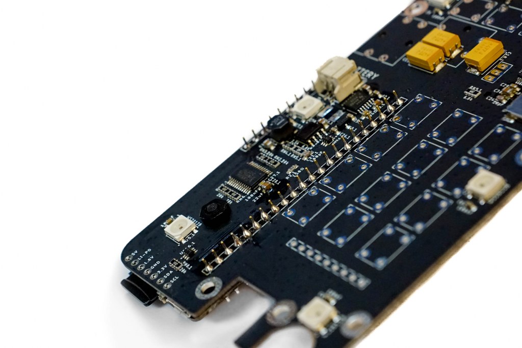 But with a steady hand and some patience, this shouldn’t be a problem for you. Step 4 – The Display board Next, we have the Display board...
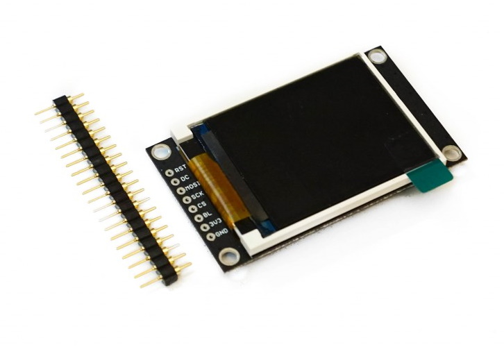
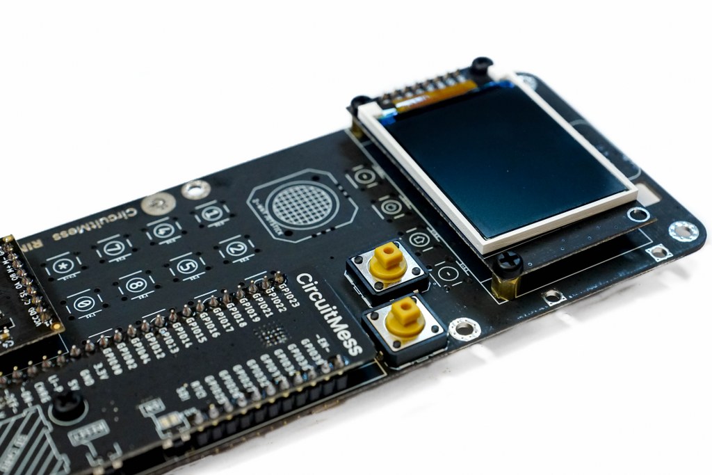
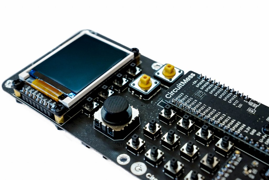
Step 5 – Mounting the Display board onto the Main board
 Place the Display board on the Main board where it says “LCD display”.
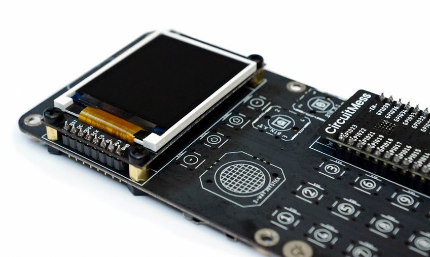
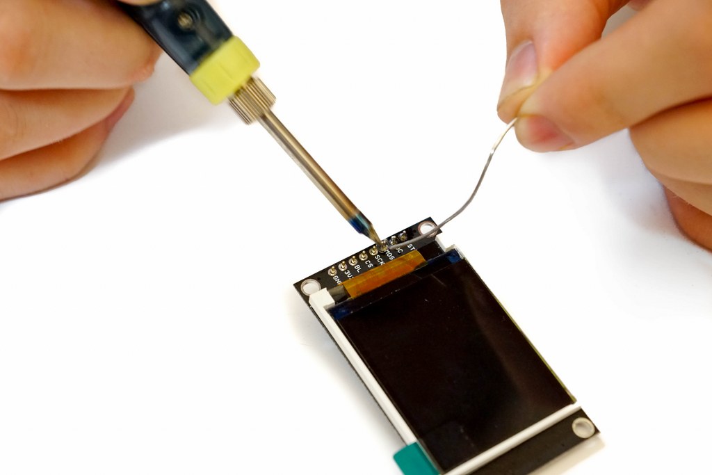
Step 6 – Soldering the Display board
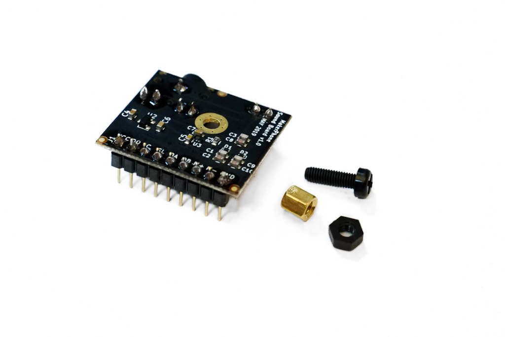
Step 7 – The Sound board
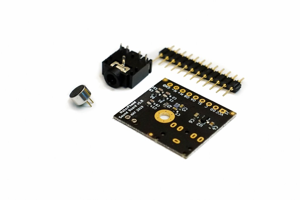
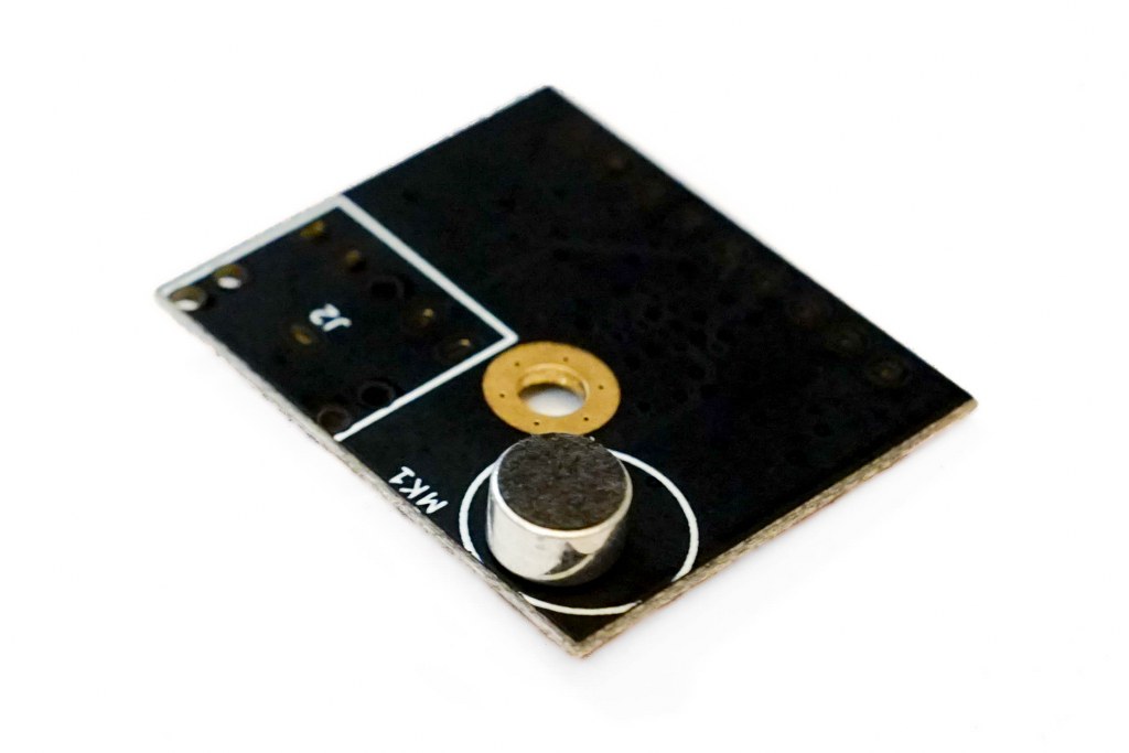
 Solder them vertically to the board just like you’ve done with the Brain board and Display board before.
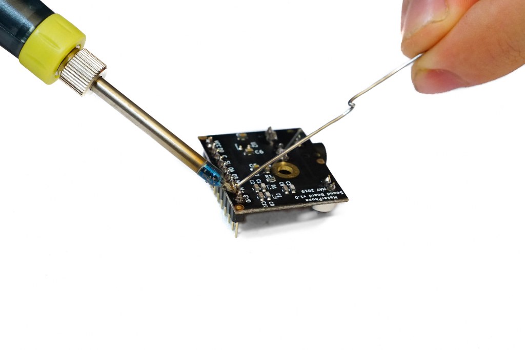
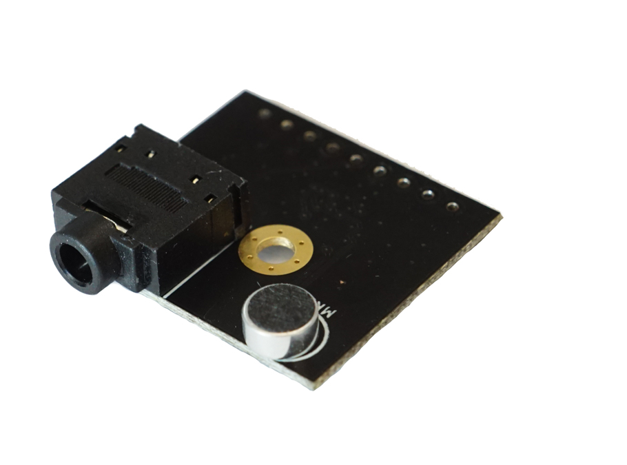
Step 8 – Attaching the Sound board
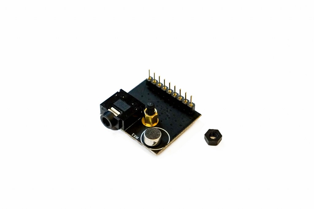 Place the Sound board onto the Main board where it says “Sound board”.
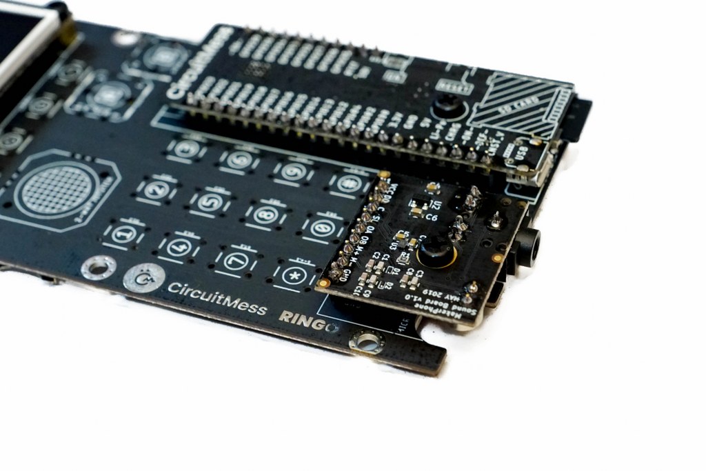
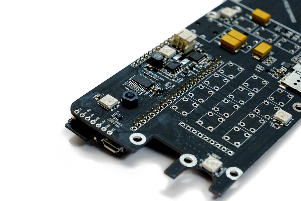
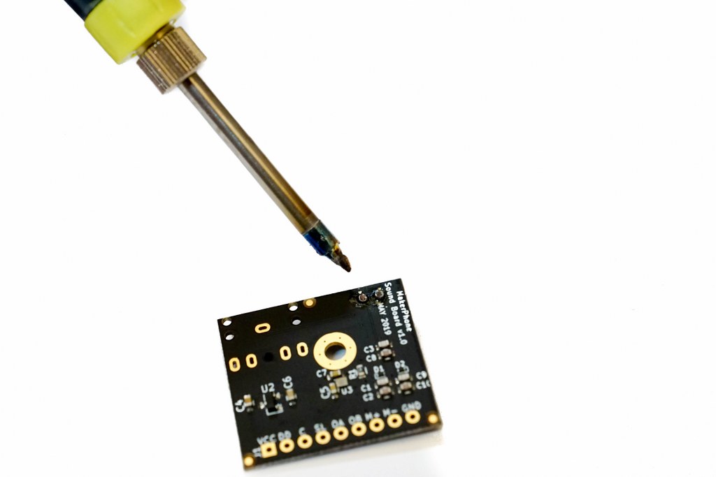
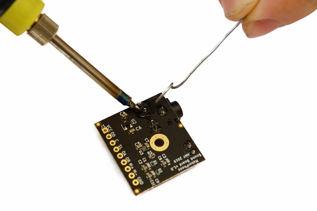
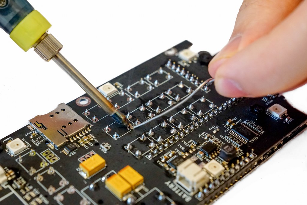
Step 9 – Soldering the Sound board
Step 10 – A lot of buttons…
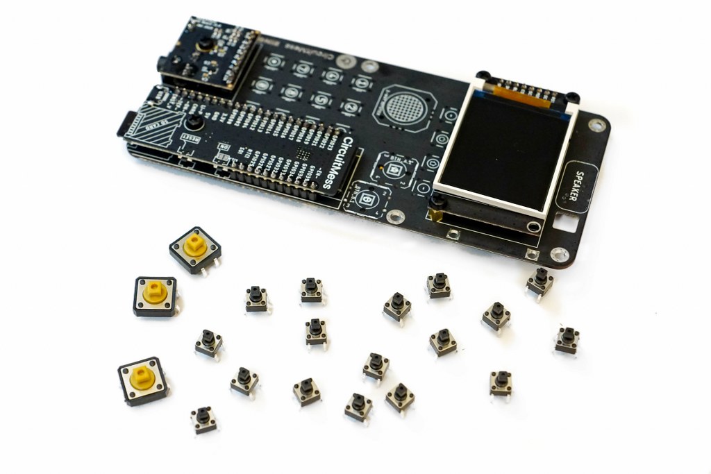
Step 11 – The joystick
Nice job so far, but unfortunately we’re not done yet. There are still a few steps ahead. 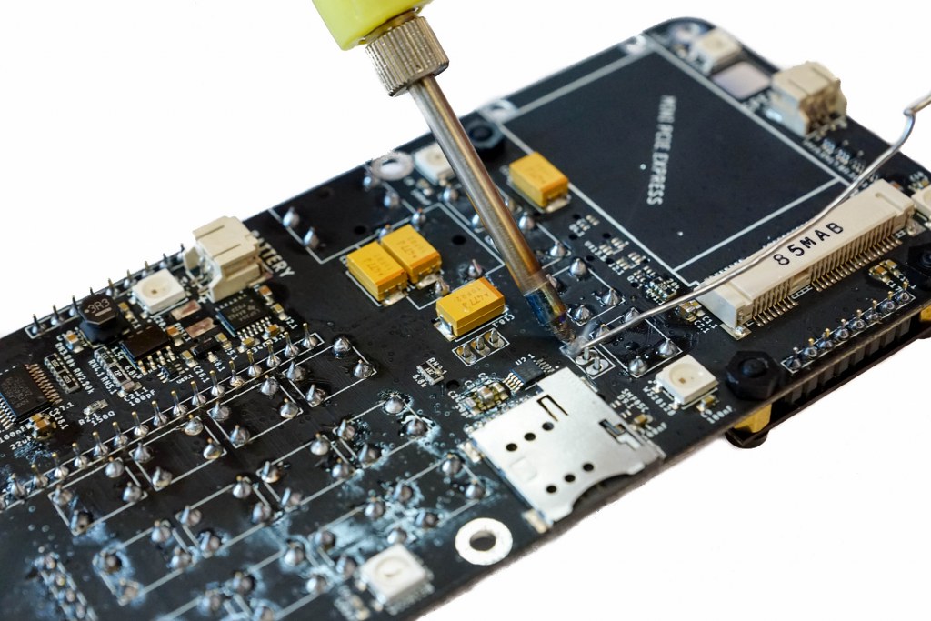
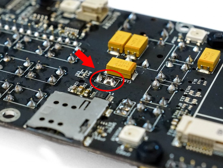
- Push down the plunger button on the desoldering pump
- Place the soldering iron on the bridged joint until it melts
- Place the desoldering pump directly on the melted solder joint
- Press the release button on the desoldering pump, that should suck up the molten solder
- Repeat the process if needed
This will require some practice, but it isn’t impossible to learn! 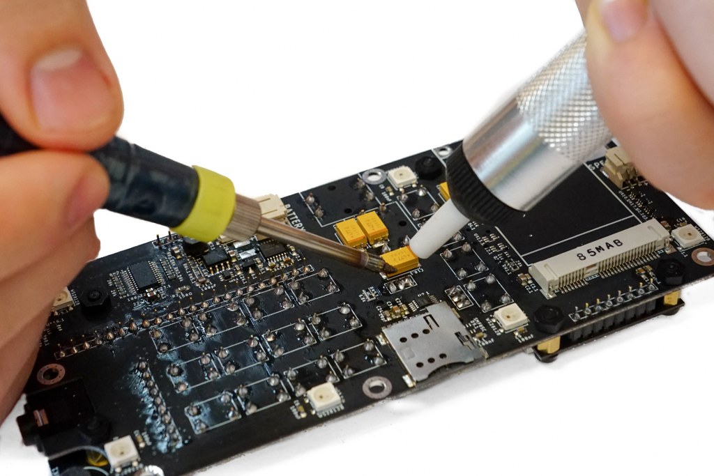
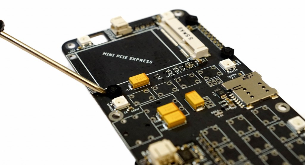
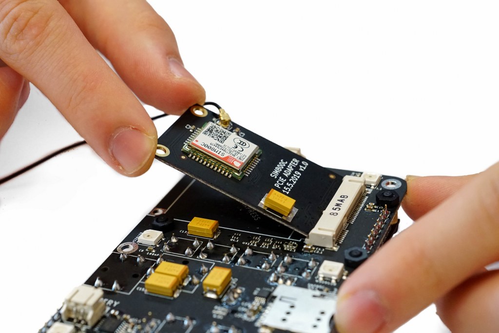
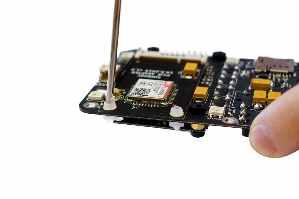
Step 12 – The Network board
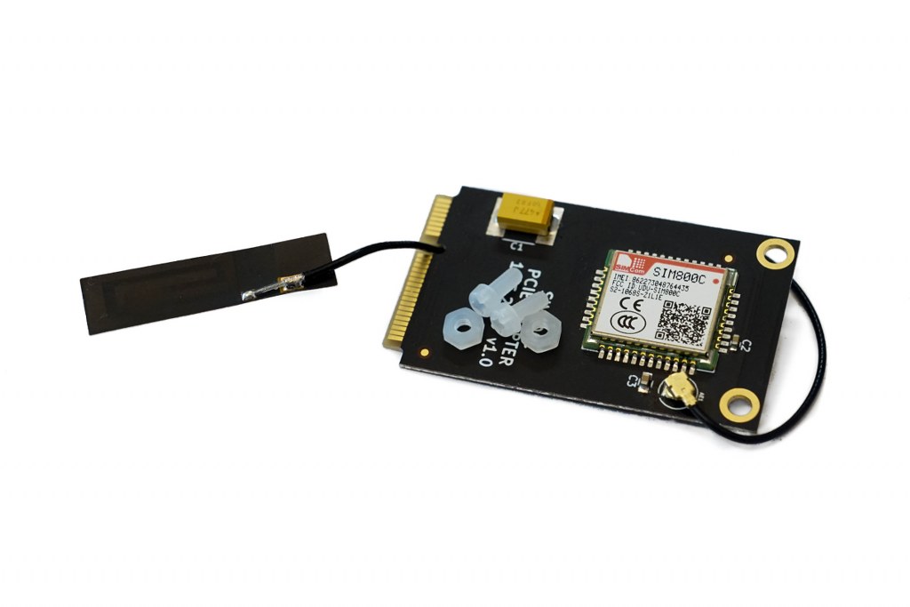
In order to attach the Network board to the Main board, you’ll need the following components:
The network module needs to be inserted at an angle like this.
Then you need to push it down until it’s horizontal with the Main board.
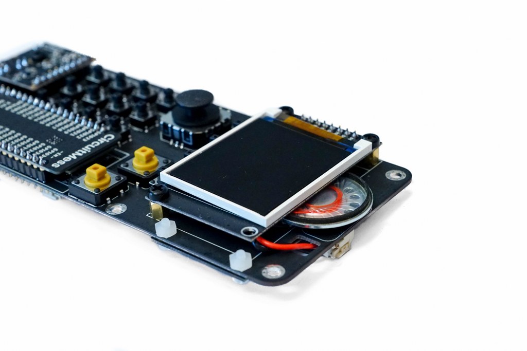
Step 13 – The speaker
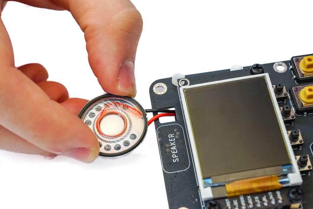
 Now, place the speaker so it fits snugly between the Display board and the Main board.