Sparkly 2.0 Guide ENG
What's in the box?

- M3x25 plastic screws
- M3x16 plastic screws
- M3x10 plastic screws
- M3x6 plastic screws
- M3x10 spacers
- M3x5 spacers
- M3x60 spacers
- Wheel axle
- Batteries
- Battery holder
- Photoresistors
- Receiver
- Token
- Wheels
- Sparkly PCB
- Electric motors
- M3x3 spacers
- M3x10 plastic screws
- M3x6 metal screw
- Antenna
- Button caps
- Transmitter
- Controller PCB
- M3x6 metal screws
- Acrylic casings for controller
- Acrylic casings for Sparkly
- Stickers
- Tires
Welcome to the Sparkly build guide!
Ready to build your very own Sparkly robo–car? Follow
these fun and easy steps to bring Sparkly to the roads!
Let’s start by getting your acrylic casings ready.

Carefully peel off the protective foil from both sides
of each casing so they are clear and shiny.


Let’s transform into
real engineers now!
The first step is to connect
the battery holder to
the PCB and insert the
batteries into the holder.
For this step, you’ll need
the following components:

Insert the metal screws
into the battery holder
as shown in the photo:

Hold onto those screws
and pop the casing on
top of the battery holder.
Make sure it’s on the
right side, just like in the
photo—this part is super
important for later!

Now you can fasten
everything together
from the back side!
If you can’t tighten it
enough with your fingers,
grab a screwdriver
for some extra help.

It’s time to set up the
motors and connect them
to the casings. This part
is a bit trickier, so we
need your full attention.
Take these components:

For each motor, we’ll
use these identical
casings, two long bolts,
and two spacers.
Start with one motor and
one casing. Attach the
casing to the part where
the wire is, just like in the
photo. The casings have
cutouts that fit perfectly
with the motor, making
it easy to assemble
everything correctly.

Now, take a long bolt and insert it from the side where the casing
is. Push it through the motor until it comes out the other side.


Add another bolt in the
same way. While holding
everything in place, attach
the second casing on the
other side, ensuring it is
positioned in the same
direction as the first.

Take the spacers and use your fingers to fasten everything together.


This is what your
first motor should
look like now:

Ensure that both
motors look exactly
like this for everything
to work properly.
Next, we’ll need both
motor parts and the
battery holder.

Let’s connect these parts together. Attach the motors to the
casing from the back side of the battery holder, ensuring the part
with the wire is positioned towards the part with the hole.


Let’s switch gears to the PCB for a moment.
Take the PCB and the photoresistors, and place them in the
left and right corners. The photoresistors should stick out
from the PCB; they don’t need to go all the way in.


Time to get creative!
In your kit, you’ve got various stickers—now’s the perfect moment
to jazz up the casings and make your final robot look cooler.
Remember to stick them on the correct sides, or
your Sparkly might end up all inside out!


Let’s begin assembling
Sparkly into a vehicle.
But before we do that,
let’s insert batteries
into the battery holder.

Be careful to put the batteries in the right way. Inside the battery
holder, there are + and – signs indicating the correct polarity.
The same + and – signs can be found on each battery.


Now we can move on to
connecting the casings.
We’ll start with this one:

As you probably guessed,
this is the side casing.
Connect it with the
battery holder on the
upper side and ensure
the narrower part
aligns with where the
wires are located.

Now, take these casings and let’s connect
everything together like solving a puzzle:


Now that we’ve
completed that step,
it’s time to connect
everything into a car.
Grab another side
casing, 3 long spacers,
3 regular spacers, and
3 medium bolts.

The bolts will go
through the three
holes of the casing, but
from the outside.

From the inside, we’ll secure them first with the smaller
spacers, and then stack the long spacers on top of those.


Before connecting the
two sides of Sparkly
together, we’ll need
to add the PCB.

You’ll notice three
connectors on the
PCB – that’s where
you’ll connect the
wires from the motors
and the battery holder
so everything can
function properly.

Here’s how you should
connect it: the far–right
connector in the photo
is where the battery
holder is connected;
the middle connector is
for the right motor, and
the far–left connector
is for the left motor.

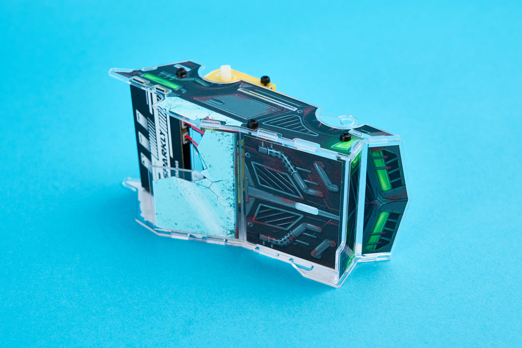
Now, take this blue
module and plug it
into the pin header
on the board.

Take the casing with the
black–green sticker and
thread the photoresistors
through the holes.
Now, connect those parts
to the rest of Sparkly.

Add the side casing part with the long spacers:

Hold everything together, then turn Sparkly to
the other side and grab three bolts.


Insert the bolts into the
three holes where the
long spacers are located.
Use the screwdriver
to fasten your
Sparkly together.

The final casing part
to add to your Sparkly
goes at the back.

To make sure Sparkly
can drive around, we
need to add wheels.
Here are the parts you’ll
need for the wheels:

First, place the rubber
tire on the black part
of the wheel. This will
ensure that your Sparkly
drives smoothly.

Now take one of the bolts
and an acrylic casing.
On the front side of the
wheel, there are two
parts where you need to
attach the acrylic piece.
Insert the bolt through
the casing and secure
it with the black wheel.
You’ll need a screwdriver
to help you with that.

Repeat this step for
all four wheels.
Then, take those
four wheels, spacers,
and six bolts.

Insert one part of the
spacer into the back side
of the wheel, then take a
bolt and fasten it together.

You might need a bit
of strength for this,
but ensure that your
bolt is tightened all
the way to the end.
Next, pull the other
end of the spacer
through the casings in
front of the motors.

Take the bolt and secure
it into the spacer to
prevent it from falling out.

Repeat this step for the second front wheel.
Mounting the back wheels is quicker and easier. Simply
connect them to the white motor part, take a bolt, and
make sure everything stays securely in place.


And you’re done!
Great job – your Sparkly is complete, and we hope you had a blast!

You may have noticed a token included in your kit. This token unlocks
a super secret game on Bit (a game console sold separately). If you’re
not using it right now, you can place it on Sparkly so you don’t lose it.

You might have noticed that there are some other
parts still waiting to be assembled. Those are for the
controller you’ll use to drive Sparkly around.
Step one: Give the controller a cool look with the
stickers of your choice. Pick any stickers you like!

Once you’re done with
customizing, you can take
a PCB, antenna, and a
round–head metal screw.

Do you see the two white
arrows pointing to one
part of the PCB? That’s
where this screw will
go. Its job is to secure
the antenna in place.
Position the antenna on
the metal part like this:

The next step is to add this
small module that handles
communication with
the module on Sparkly.
This communication
allows you to navigate
Sparkly around by
clicking on the controller.

You have to connect it to
the pin header like this:

Now, take the coin
battery and place it in the
battery holder with the +
sign facing towards you.

It’s time to add the casings. Let’s start with this one:


Now take the second identical casing and place it on top of this one.
You may have noticed that we’re missing the pushbuttons –
well, the mechanical parts of them are already on the PCB,
and now we’ll add the caps so you can click on them.


To secure the pushbuttons in place, we need
to add another casing on top.

Take the biggest casing
and place everything on it:

Take one bolt and use it
to screw all of the casings
and the board together.

Secure it at the back
with a spacer.

And you’re done!


Give Sparkly a spin!
To turn on your Sparkly, click the on/off switch
located on the right side of the PCB.
Sparkly has two driving modes:
1. Controller Mode: If you want to drive it using the controller, set the left–
most switch to the controller mode, and turn on your controller. Then, click
on pairing on Sparkly to connect it with the controller, and you’re ready to go.
2. Light Mode: If you prefer Sparkly to drive away from light sources,
switch the left–most switch to the side with the bulb icon. Use
your phone or any light source and point it at the photoresistors on
Sparkly’s back. Sparkly will move around, avoiding the light source.
That’s it! We hope you had a great time building Sparkly and its
controller, and that you learned something new along the way.