Build your Spencer
Ready to start soldering?
In this guide, we'll show you how to put together all the cool parts step by step. Don't worry – we've included lots of pictures to make everything super clear and easy to follow.
Part One - Soldering the first two components
Here are the components you will need for the first step. Take your LED board and two female pin headers that you see in the photo below.

Flip the LED board over and find the holes on top. These match the spots for your pin headers. You'll see two holes – one on the left and one on the right, right above the display.
Carefully insert the pin headers from the back of the board, just like in the picture.

Now, turn the board around and hold the pin headers in place.

It's time to solder!
Place the soldering iron on the first pin for about ten seconds until it heats up, then add the solder to it.


Before you repeat this step for the other pins, let's make sure your pin header sits at the right angle.
If you think your pin header is not soldered at the right angle, take the board and, while holding it, reheat the component so that it sits straight.
To resolder the header, you simply need to place the soldering iron tip to that one pin that you just soldered and adjust it with your finger as soon as the iron melts the solder. Once you remove the soldering iron tip, the solder should cool off and stay as it is, holding the header straight.
Repeat the steps for the second pin header.
Turn the board upside down again and insert the component. After that, start with soldering the first pin and then adjust the header before soldering all the rest.


Part Two - Male pin headers
Now we'll work with male pin headers.
Grab your PCB and two male pin headers.

Place the male pin header as shown in the picture.
Ensure that you place it on the side where all the components are located. Also, pay attention to pull the slightly rounded part through the PCB:

Turn the board over and start soldering.


Repeat the step for the second male pin header.


Part Three - Resistor
Time to add a resistor!
You'll need your main circuit board and the resistor.

Fold the resistor's legs so that they bend exactly where the resistor is.
Take a look at the photo below.

Put the resistor on the board, making sure it's on the right side.


Turn the board over and solder the resistor.

Once it's nicely soldered, snip off the extra leg length with pliers.
Always keep the part you are cutting away from your eyes:

Right now, the board should look like this:

Part four - soldering the pushbutton
Now we'll add the pushbutton and LED. Get your main board, pushbutton, and LED ready.

Place the pushbutton on the board as shown.


Then, insert the LED into the pushbutton like this:

Check the LED's polarity.
The LED's longer leg is positive (+), while its shorter leg is negative (-).
When you turn the PCB around, you'll notice + and - marks indicating where the LED legs should be placed.
If you don't turn the LED the right way, it won't work.


Flip the board and start soldering.


When you're finished, use the pliers to cut the LED legs off.

Right now, your PCB should look like this:


Part five - Soldering the capacitor
Next up, the capacitor!
Get your PCB and the capacitor.

The capacitor, unlike the other components, will be placed on the back of the PCB and soldered on the front.
Just like this:

Polarity is marked with black and white on the capacitor and on the board, so make sure to put black on black and white on white.
Otherwise, your capacitor will not function.

Turn the board over and start soldering.

When you're finished soldering, cut the capacitor's legs:

Right now, the PCB should look like this:


We're done with soldering! Congrats.
Check that all soldering joints are looking good, and if so, turn off the soldering iron. Let it cool for 10 minutes on a stand.
Part six - The speaker
Let's set up the speaker. Take your speaker and the PCB.

Connect it to the following connector:


Part seven - Acrylic casings
These are the big casings that should have been included in your kit:

Remove the protective foil from both sides of the casings before using them:


Finally, all of the casings should be completely transparent.

Now, take these parts:

The casing should be placed this way onto the speaker:

Insert the bolts through the front side and tighten them with the medium size spacers on the backside.

Take the LED board four bolts, four medium spacers and four small spacers.

Put the bolts like this:

Use the small spacers to attach them from the other side:


Repeat this step for all spacers and take the LED board.

Now, using the medium spacers, attach it like this:


Right now, the LED board should look like this:


Take the arms and legs, as well as the stickers.

You have to remove the protective foil from them.


Put the stickers on them and be sure to put it on the right side:


This is what you should have at the end:

Now, take the parts from the photo below:

Take the leg and the casing and connect them like this:

Pull the bolt through both of them like shown here:

Attach it with the medium spacer like this:


Take three of the longest spacers and connect them like this:


Put this part aside for a moment.
Take the arm and the casing.

Take the bolt and put it through the arm:

Take the big spacers' part and fasten it on the bolt with your fingers:

Now take the other identical casing, and the second arm and leg. We'll also need two bolts and one medium spacer.
Repeat the previous steps for these components:

Connect it with the previous casing like this:

This requires the use of a screwdriver.
It's finally time to connect all of the casings to Spencer.
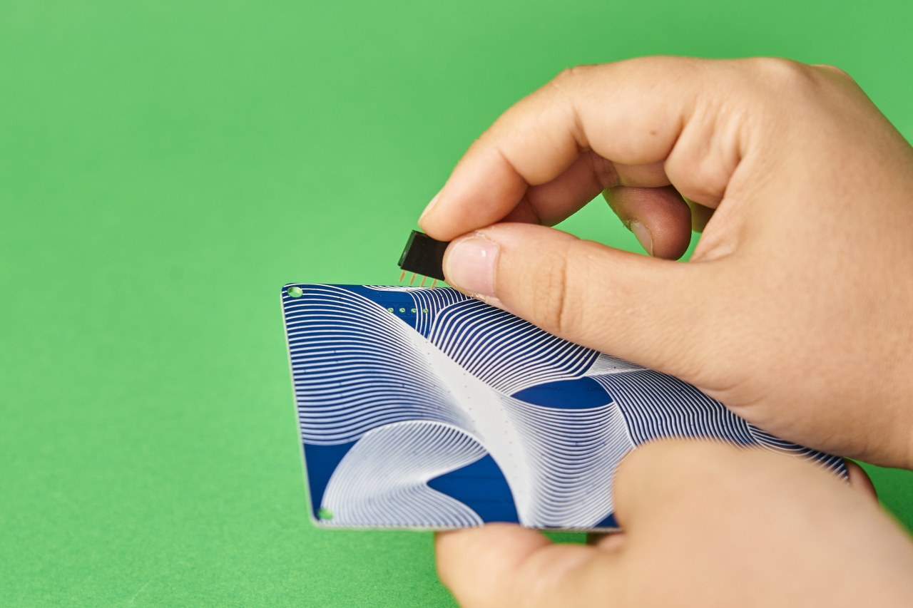
Connect the female and male headers first:

And connect it to the rest of the casings:


Take this casing and put it on the top:


Take this casing and put it on the bottom:

Make sure that nothing is falling off.
Amazing!
You're almost done!
Grab those little pads and stick them to the bottom casing like this:


Lastly, let's put the red button cap on the pushbutton:

Congrats!
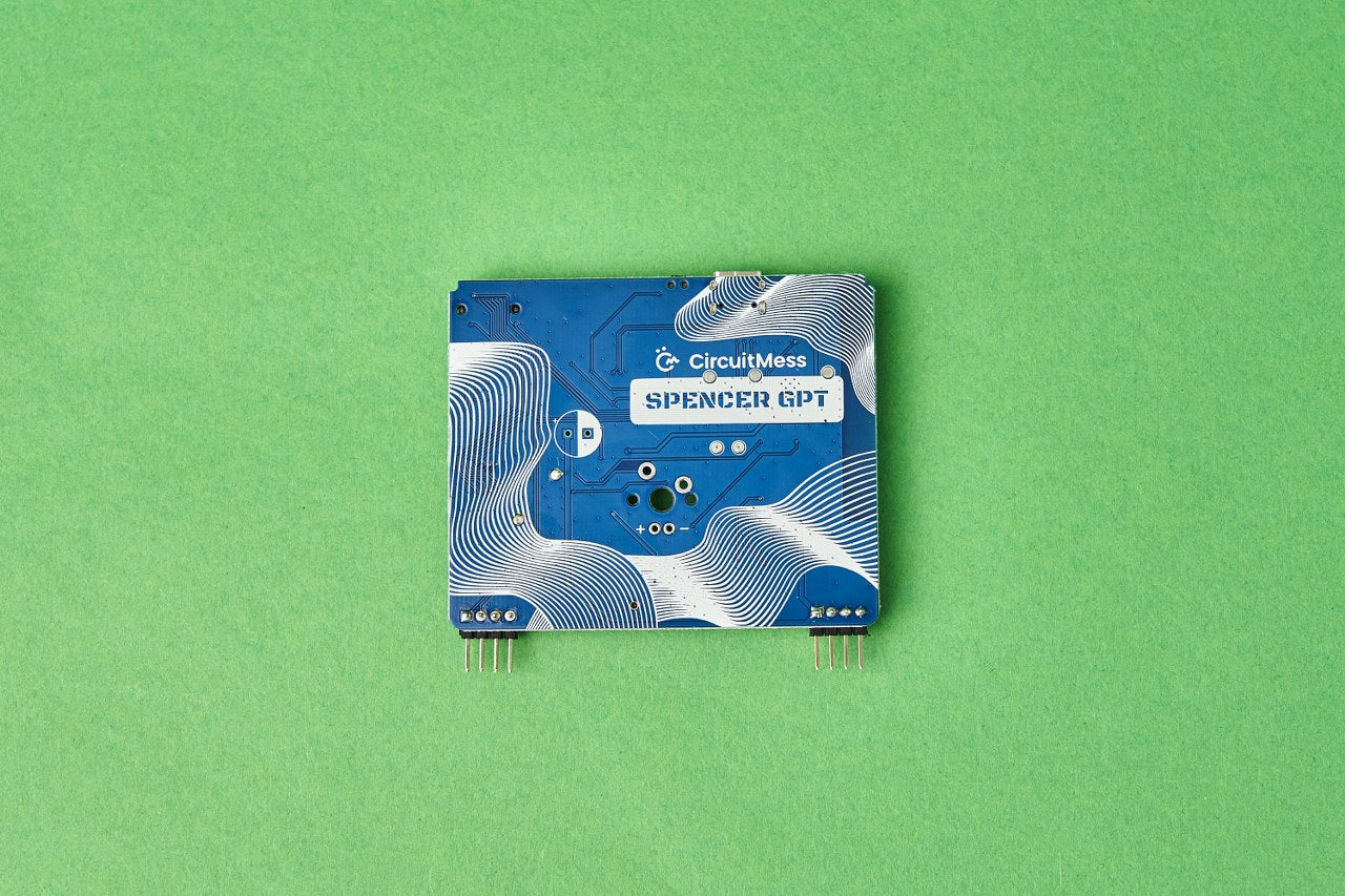
You've successfully built your Spencer and it looks like this:

Now, connect it to your computer and start chatting!
If you run into any problems, don't worry. Just reach out to us at contact@circuitmess.com, and we'll help you out.